Retopologize
Introduction
Retopologize is a reference mesh feature which helps you create automatic retopologized meshes.
Most of the times, the retopologizing is done via manual methods, especially for production ready assets, where exact vertex placement and edge flow are crucial. It's not recommended to use automatic retopology on such assets, because you may end up fixing key areas and most likely spend more time than if you'd retopologized by hand.
However, for certain parts (such as the ears) or entire meshes (such as static, non deformable objects), automatic retopology is a good alternative.
Basic Usage
First, you must have a clean, non-manifold reference mesh, with no duplicate triangles or vertices.
A mesh is non-manifold if any of its edges share no more than two faces.
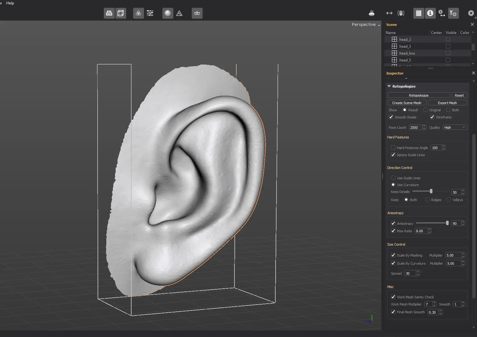
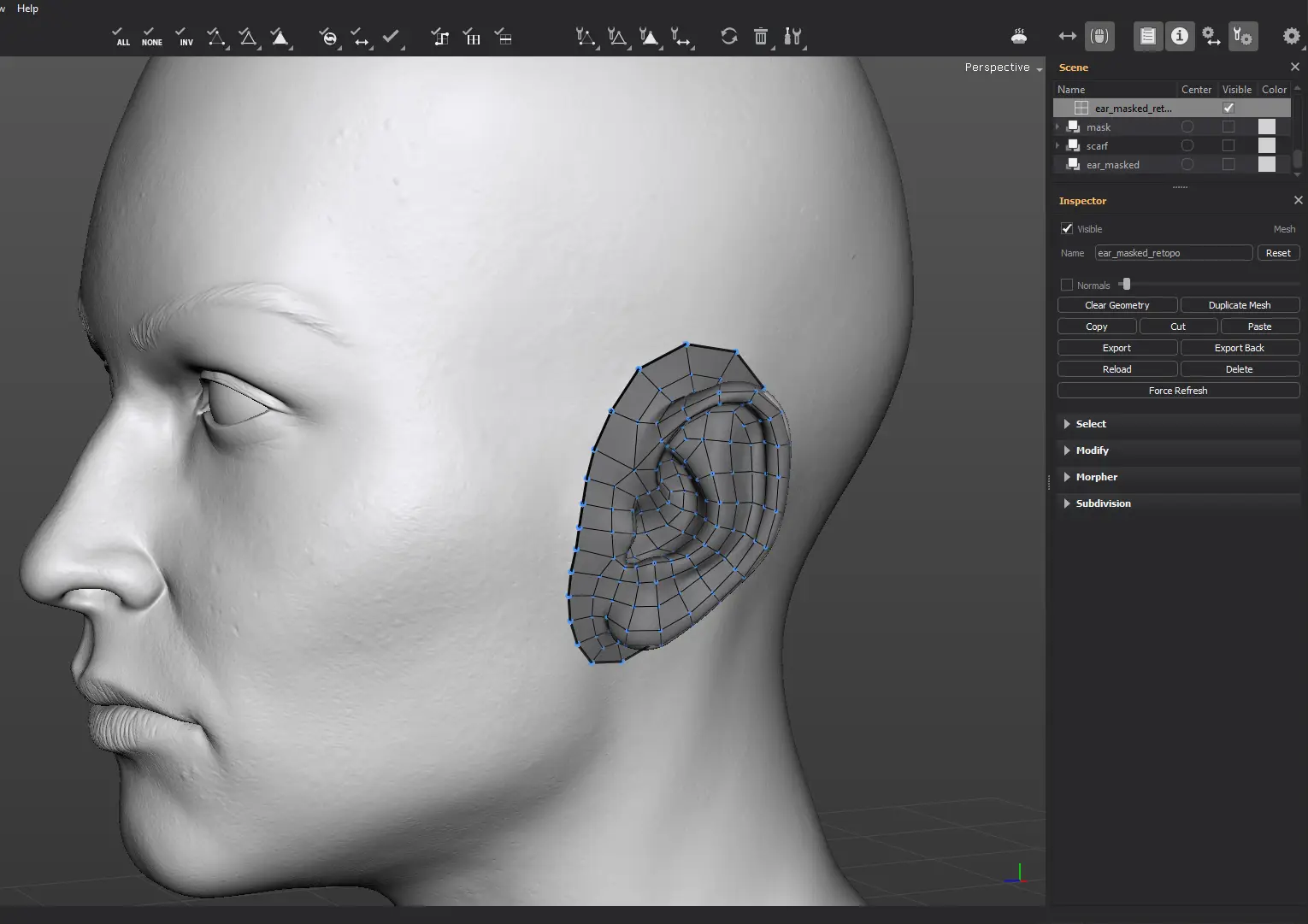
In this example, we'll retopologize the ear, separated with the Extract feature.
Start by selecting the reference mesh, then locate the Retopologize panel in the Inspector View.
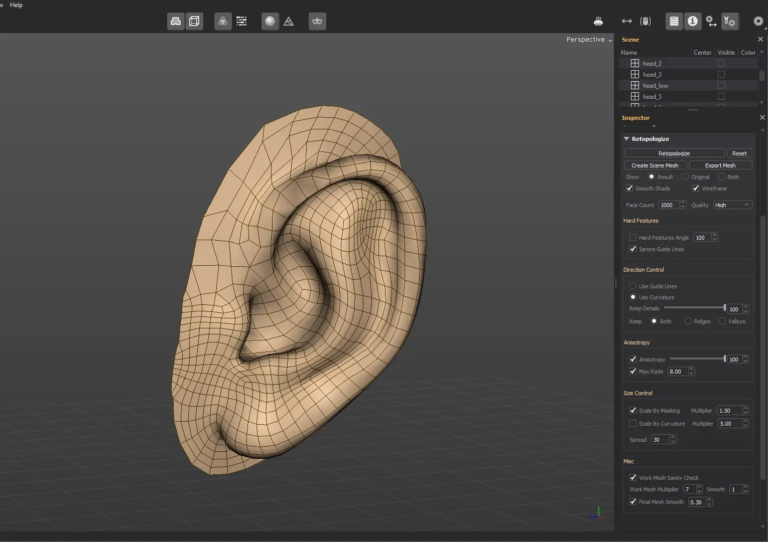
The default options work just fine, the only parameter you need to adjust is the desired approximate face (quads) count.
Click on the Retopologize button. A preview mesh will be displayed instead of the reference mesh. If you're not happy with the result, press the Retopologize button once more.
Each time you click on the Retopologize button, a completely different retopologized mesh will be calculated.

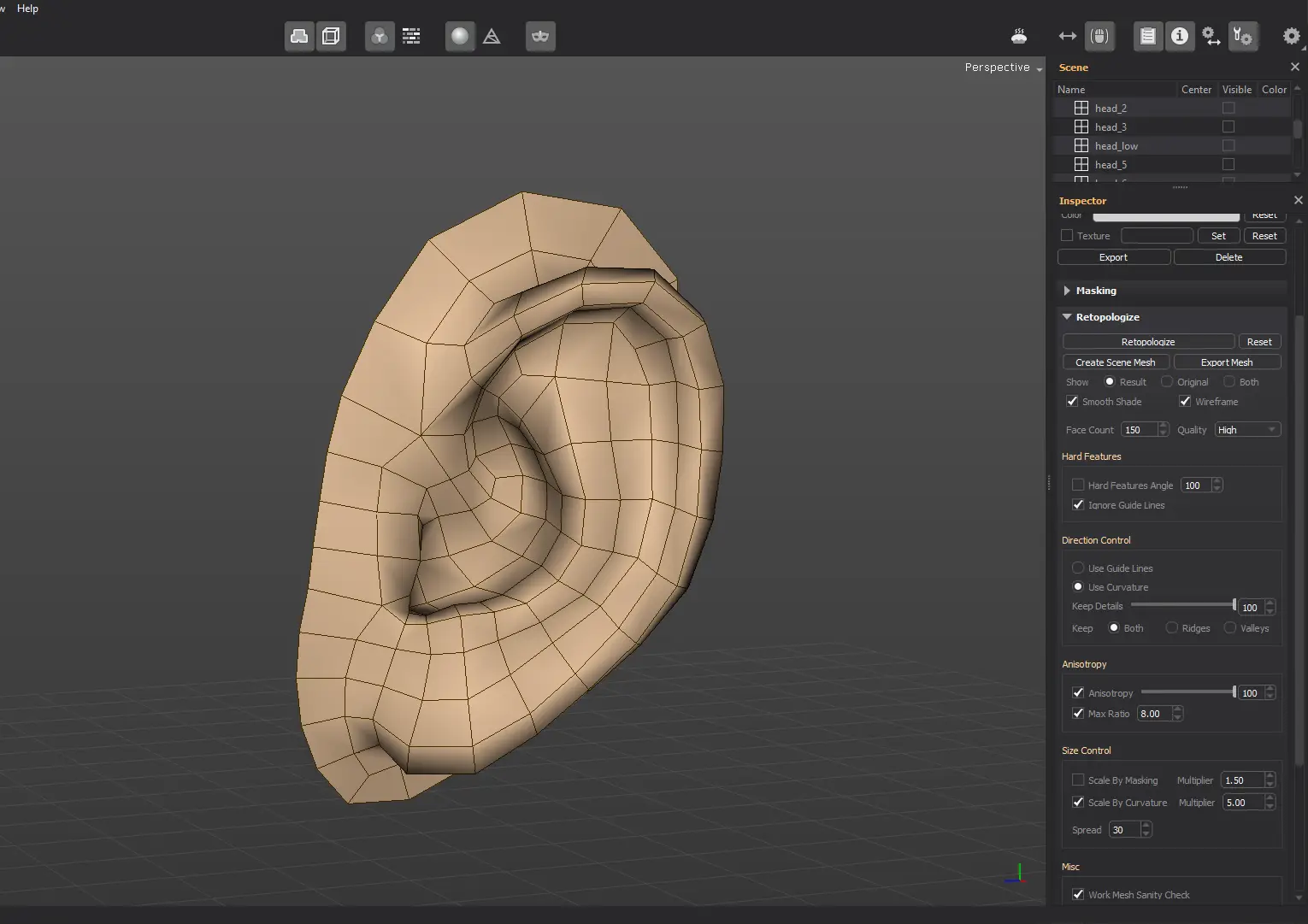
Tweak the desired approximate face count until you're fine with the retopologized mesh polygon density.

Once you obtain a good retopologized mesh preview, it's time to either export it or add it to the scene as an editable mesh.
Click the Export Mesh button to have the mesh exported.
In case you want to create a mesh from the current automatic retopology, click the Create Scene Mesh button.
A mesh is created under the active reference mesh.
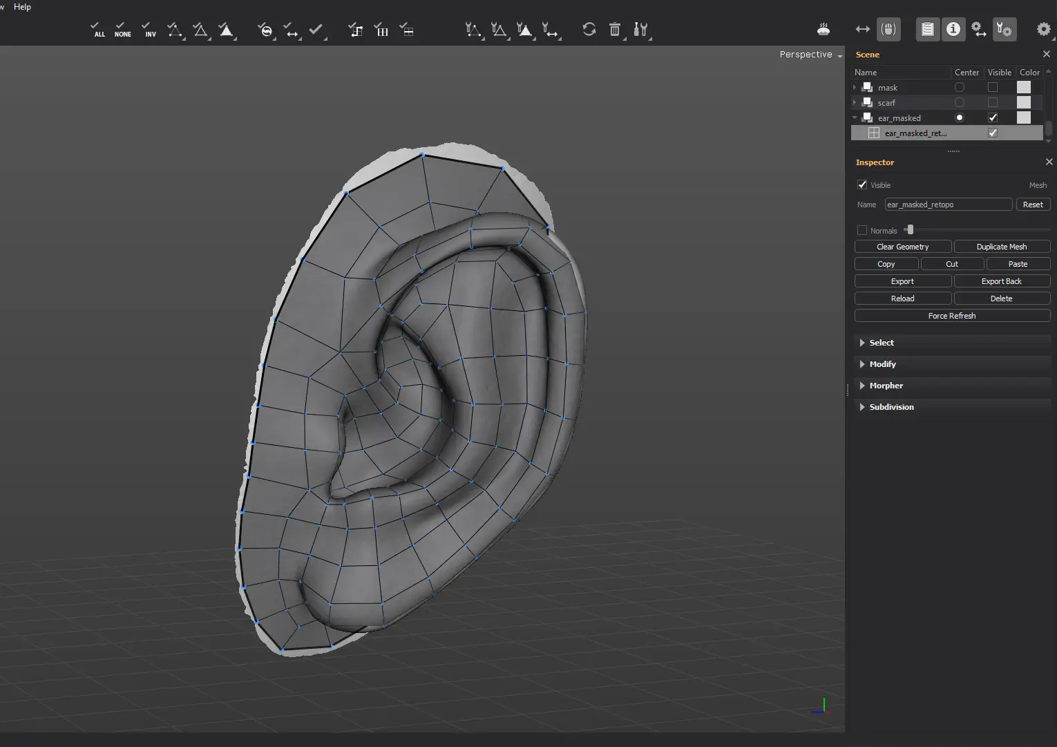
You can move the mesh under the head reference mesh and continue editing it from there. You can merge it with any existing mesh you have created before.
To merge more meshes into a new one, make them visible and hide the rest. Then, click on Merge Visible in the Mesh menu.
Hard Features
In case the reference mesh has some hard edges you want to maintain when using the Retopologize feature, enable the Hard Features Angle option. All the edges connected to faces that make an angle less than this value, will have corresponding aligned edges in the retopologized mesh.
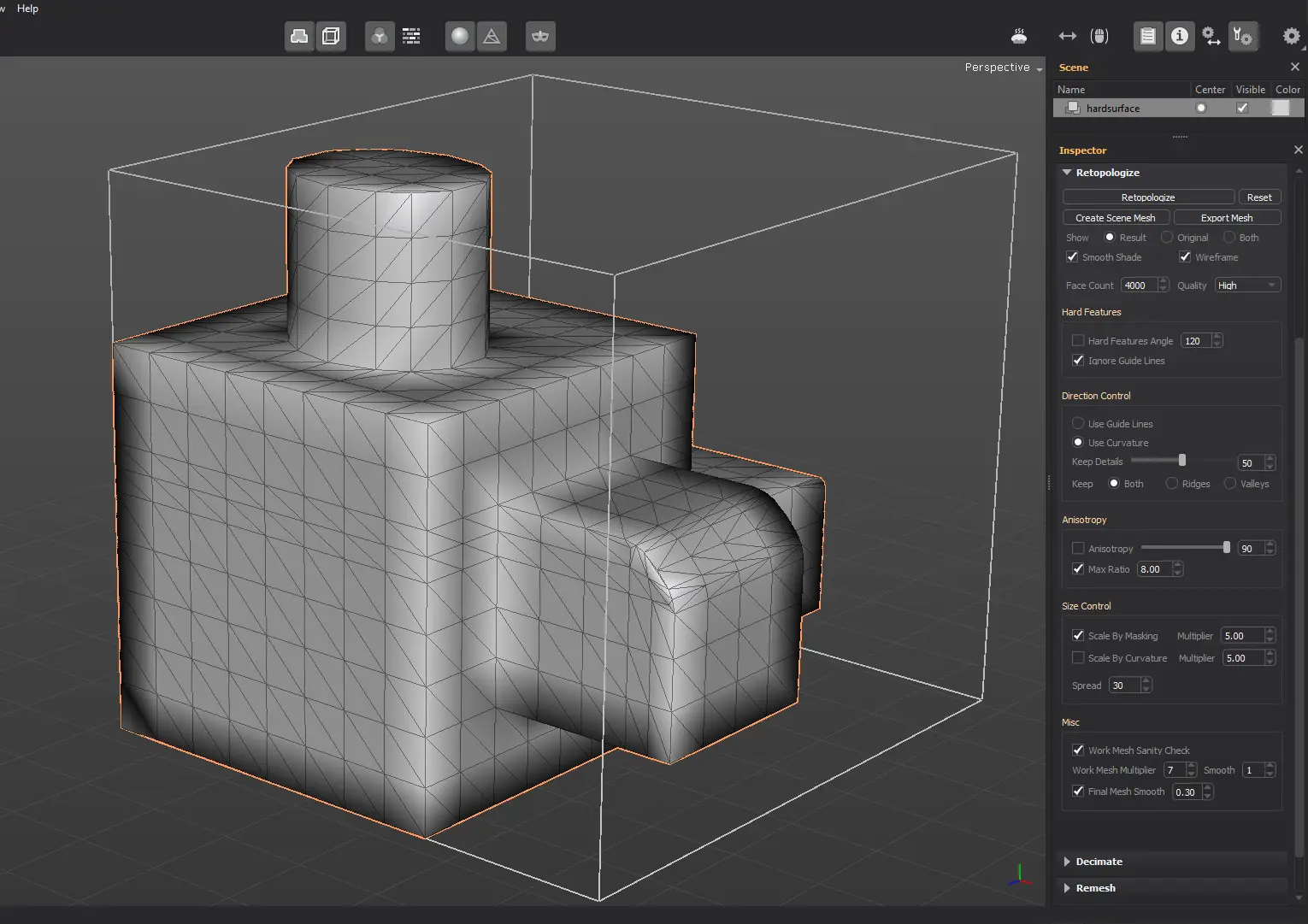
Notice how the retopologized mesh looks like by default, when the option is not enabled.
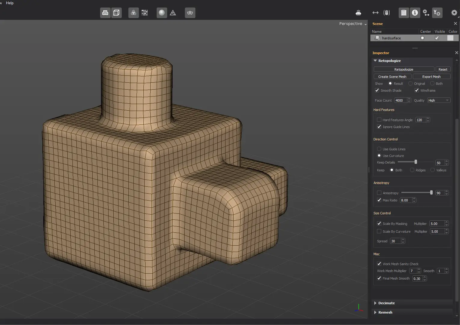
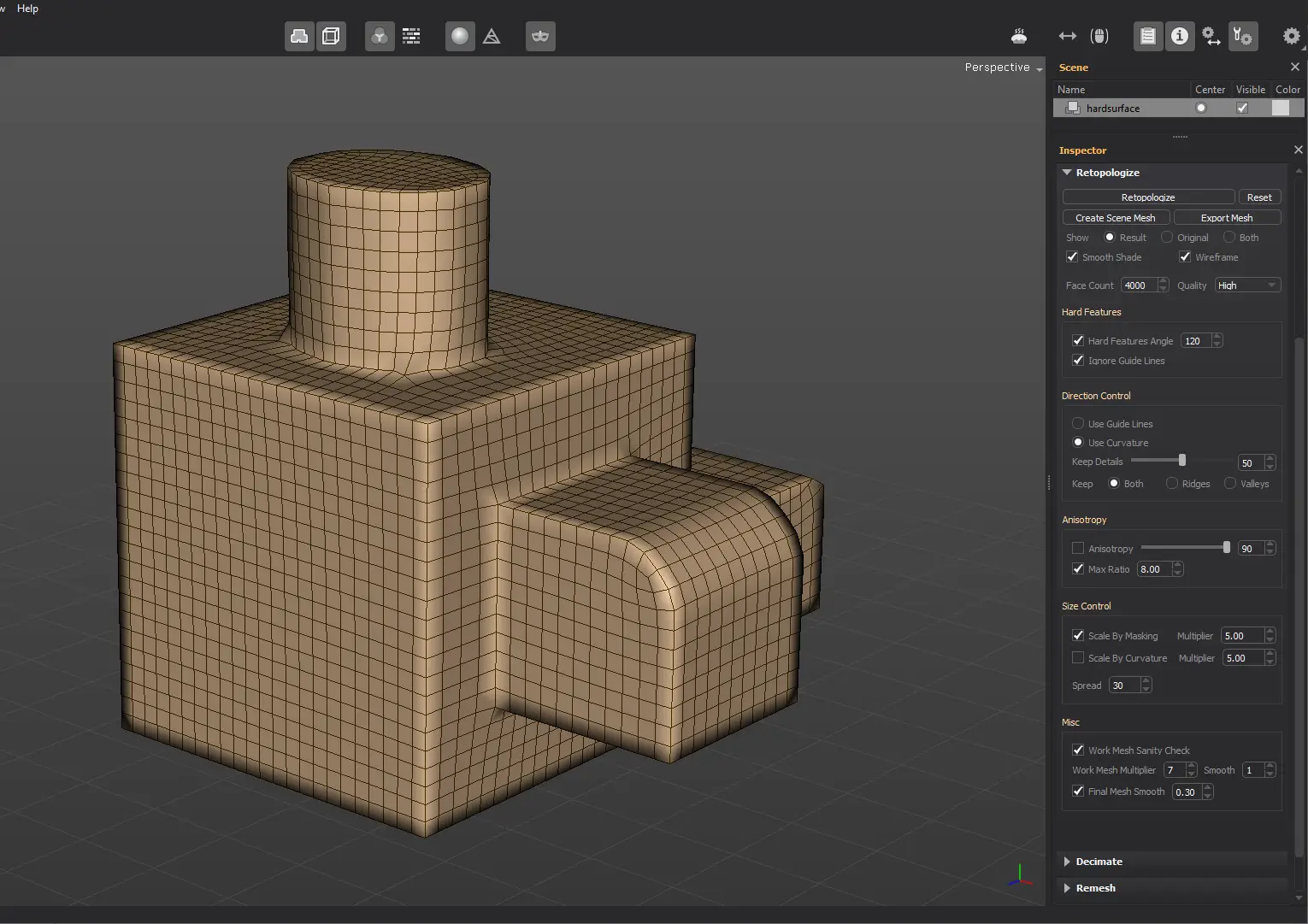
Once you activate the Hard Features Angle option, the retopologized mesh will be aligned with the hard features/edges.
Direction Control
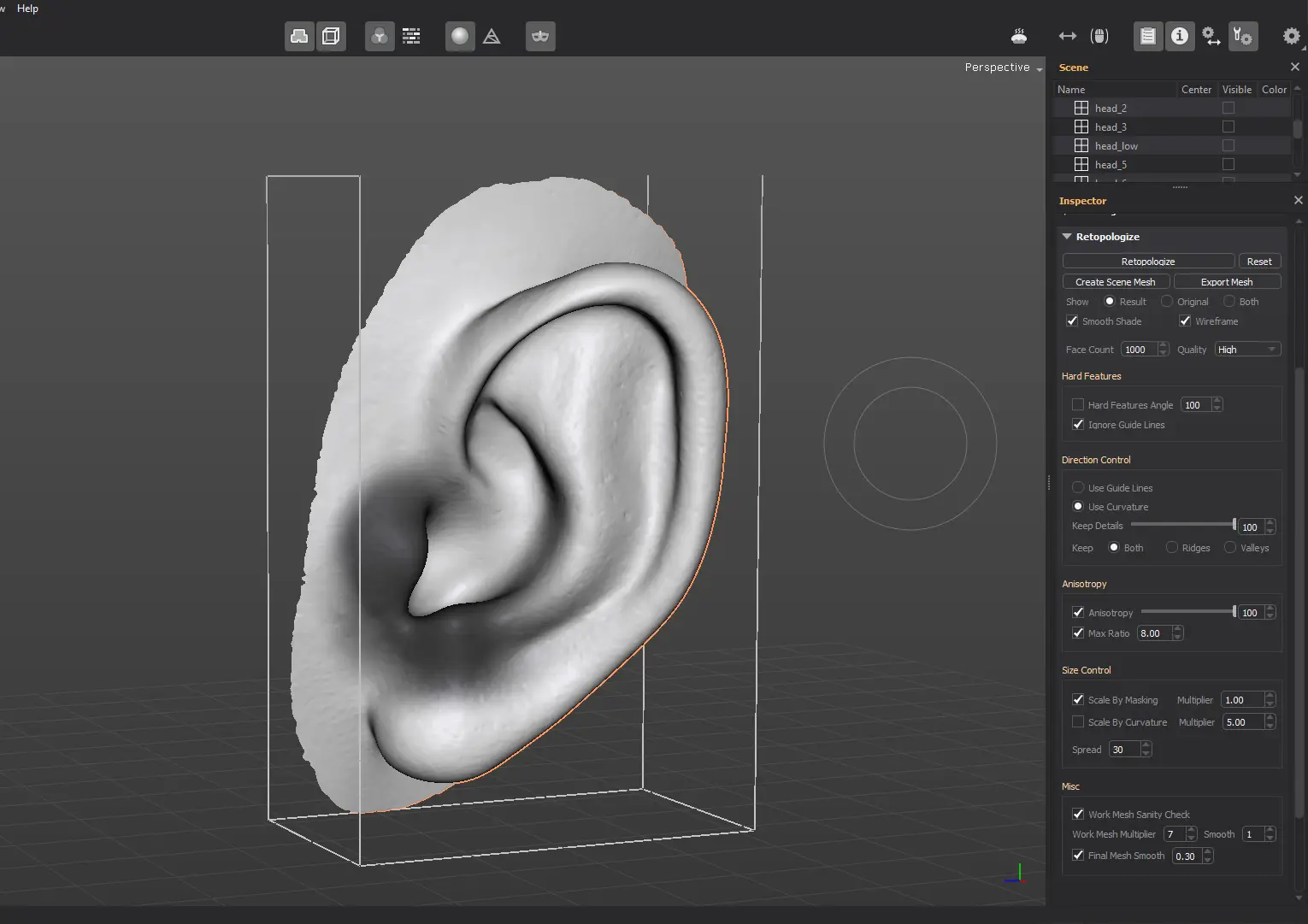
By default, Retopologize analyzes the mesh curvature and directions, in order to create the edge flow. The results are predictive and the default options are a good starting point.

In case you want to control the edge flow yourself, then you can use Guide Lines to define it.
Start by drawing the direction strokes using the Guide Lines tool. Then change the Retopologize Direction Control option from Use Curvature to Use Guide Lines.
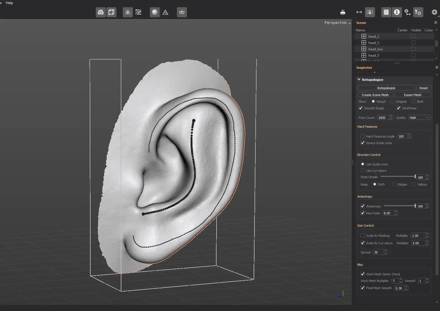
The resulting retopologized mesh will have the edge flow similar with the one defined by the guides.

Anisotropy
This feature modifies the edge lengths on a face basis, based on the underlying curvature. The more the reference mesh under a polygon is curved over a direction, the shorter the edges get, so the resulting retopologized mesh packs more details over curved areas.
Areas with low anisotropy tend to produce quads with equal edge lengths. The higher the anisotropy, the bigger the difference between neighboring edges.

As you lower the Anisotropy value, the edges tend to be more uniform in length.

And finally, if you turn Anisotropy off, the resulting faces will look more like squares, with equal edge lengths.

Size Control
By default, Retopologize scales the resulting faces based on the reference mesh local curvature. In areas where there are more details, the polygons get smaller. This ensures that the faces are spread and sized in such a way that the details are captured optimally, provided the limited face count.

If you disable the Scale By Curvature option, the resulting faces tend to have more uniform areas.
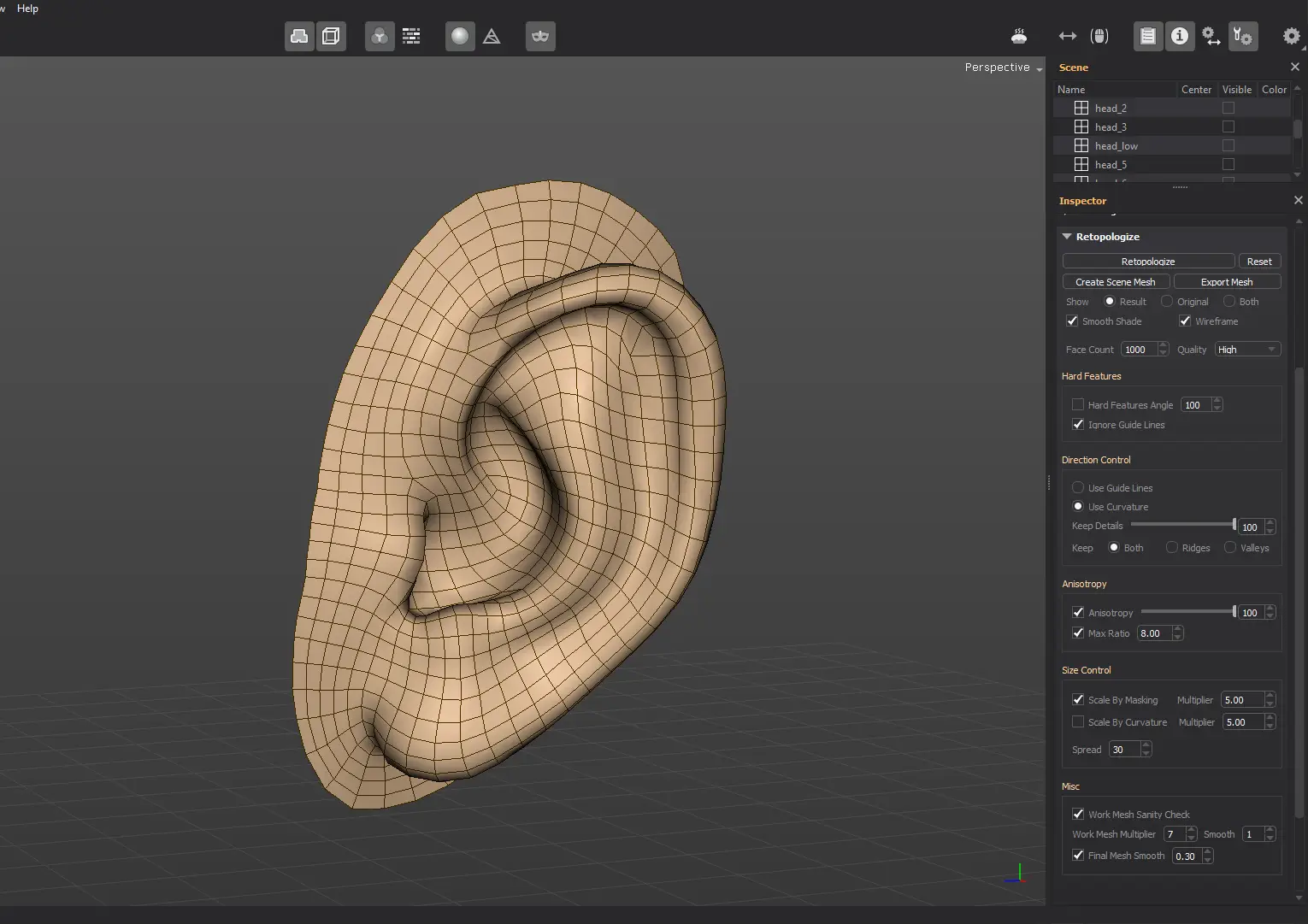
Scale By Masking scales the faces down based on the underlying reference mesh masking values.
You can paint the masked areas using the Mask reference mesh tool.
Use this feature with caution, as the results are not always predictible, especially if there are high contrast masked areas.